
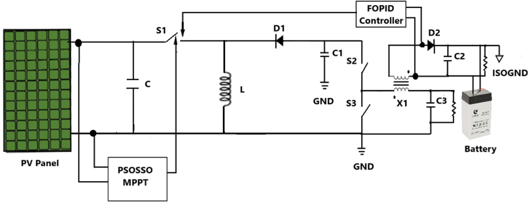
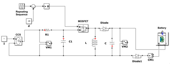
Pv System With Mppt Circuit Download Scientific Diagram
By varying these parameters, the power can be maximized To maximize the output power generally, MPPT is used There are several MPPT method exists in order to maximize the Simulation and analysis of perturb and observe mppt algorithm for array using Asoka Technologies MPPT Poster Christopher R Poniatowski Implementation of mppt algorithm on pv
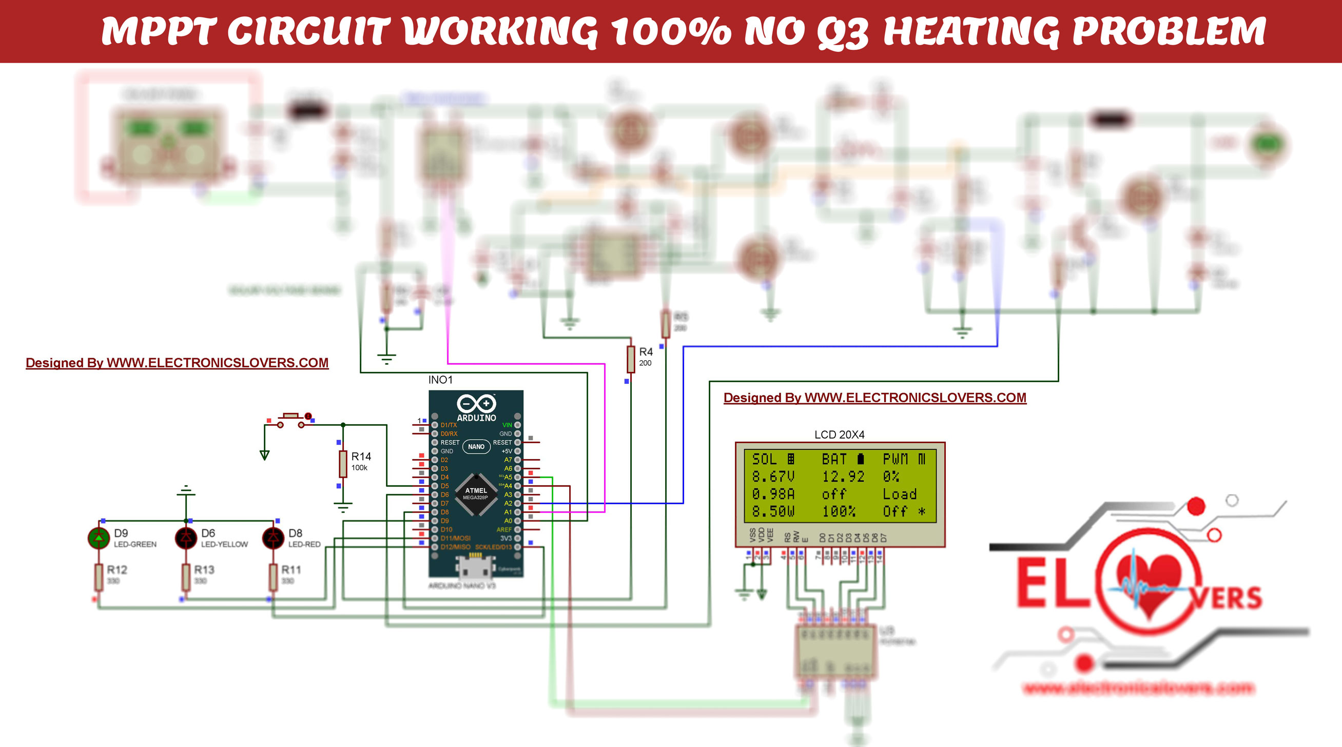
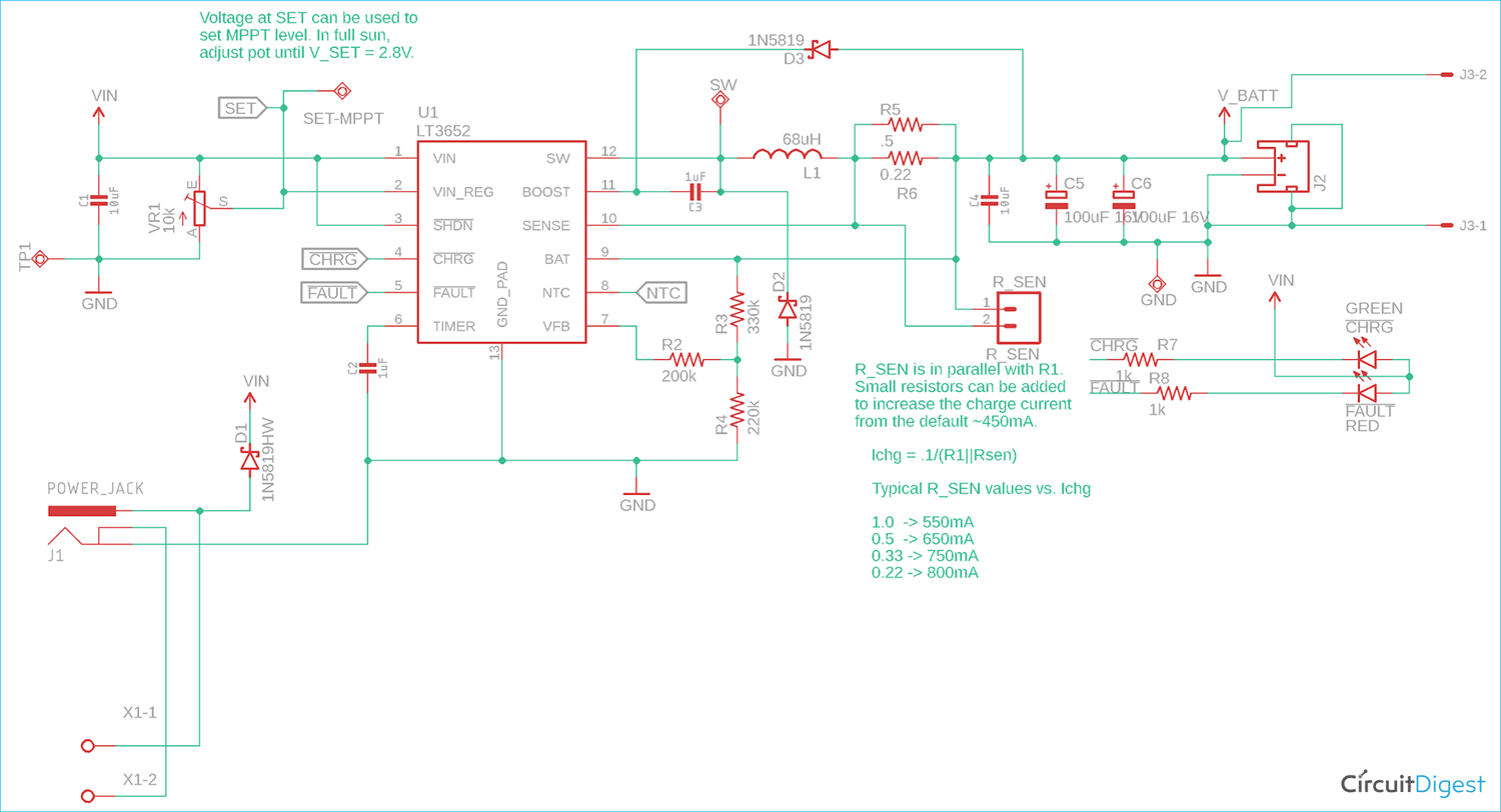
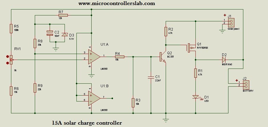
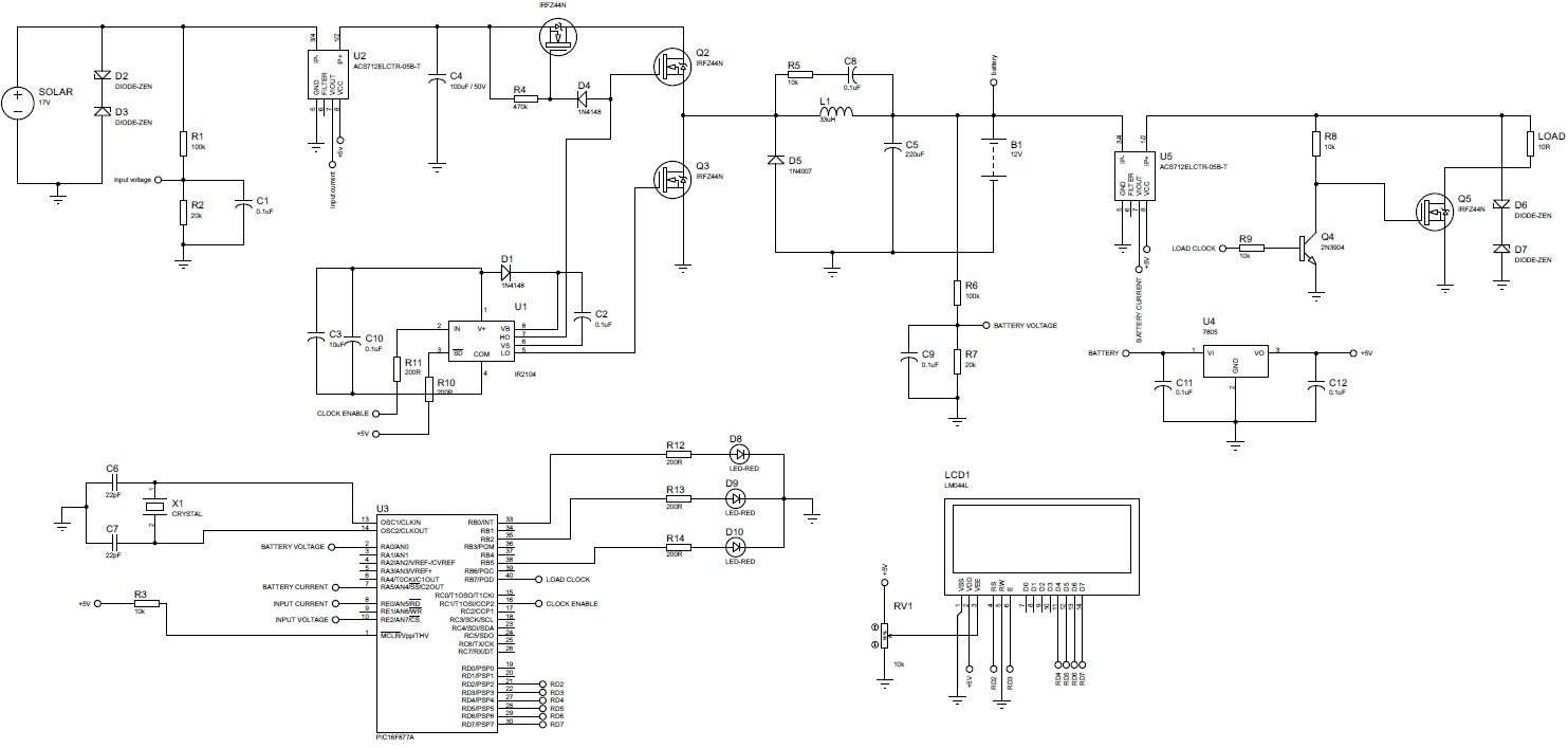
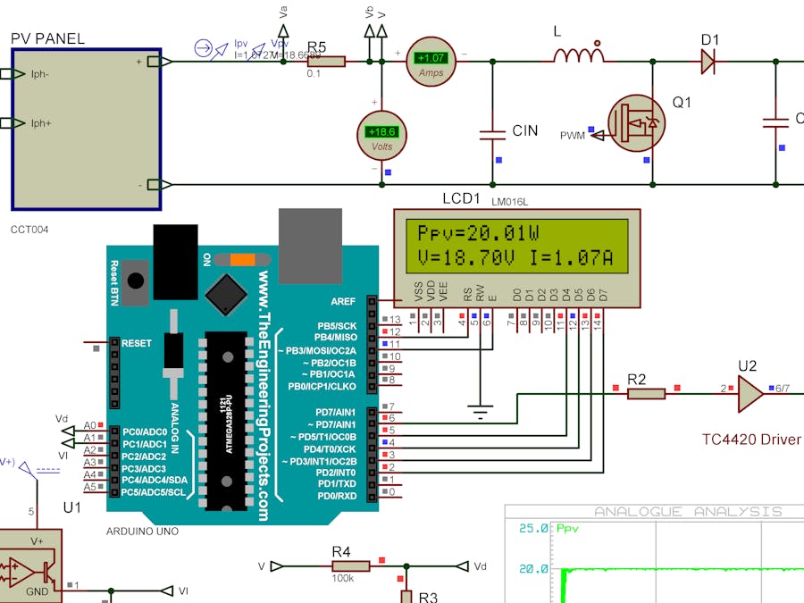
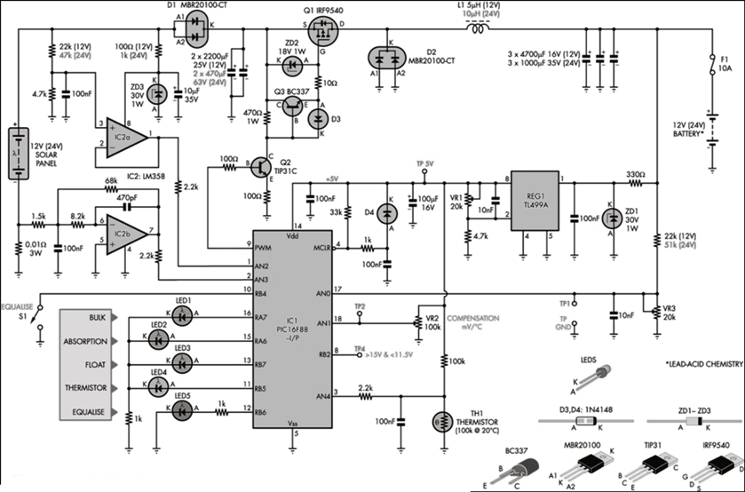
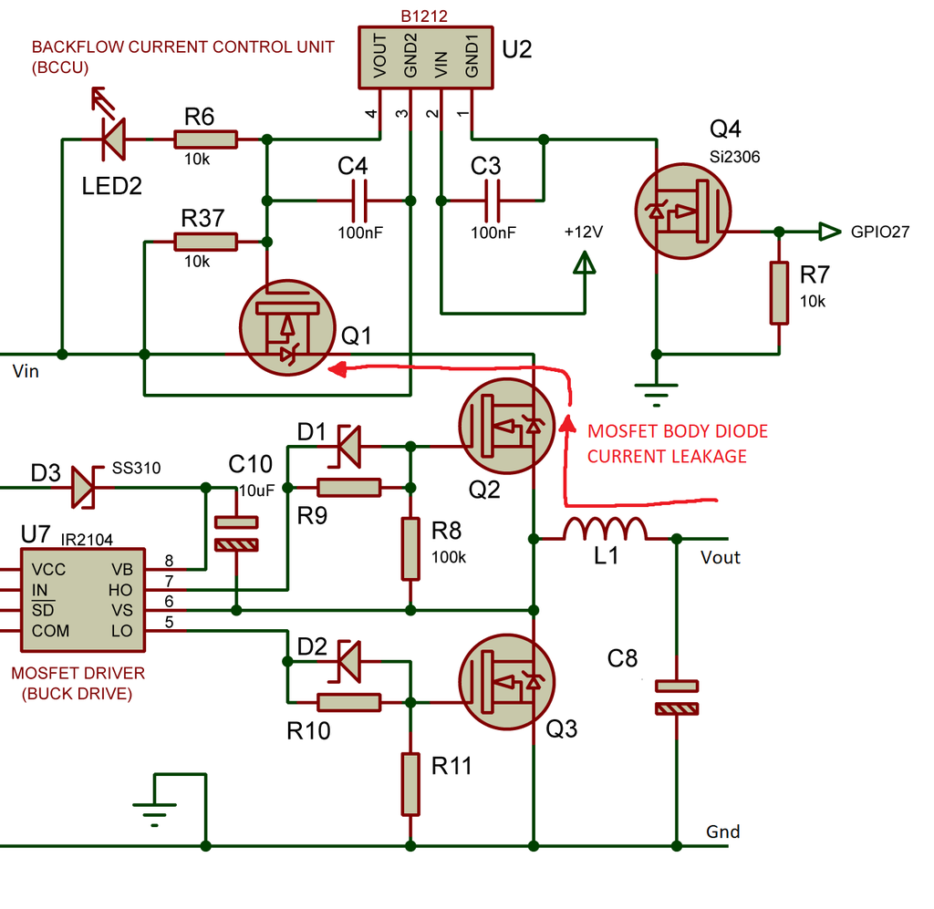
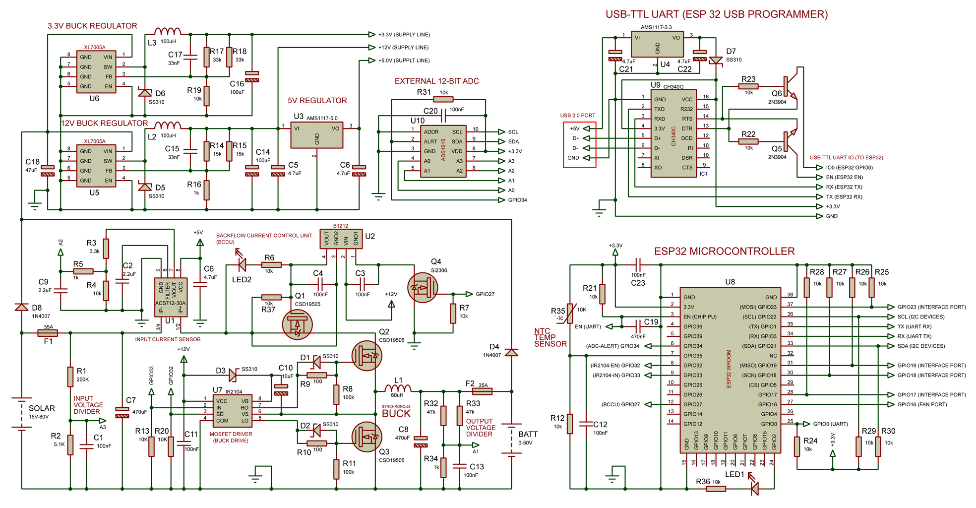
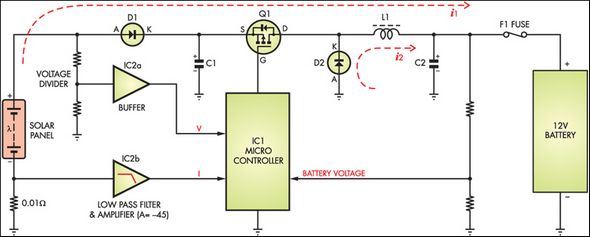
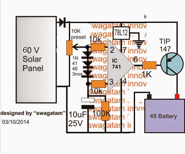
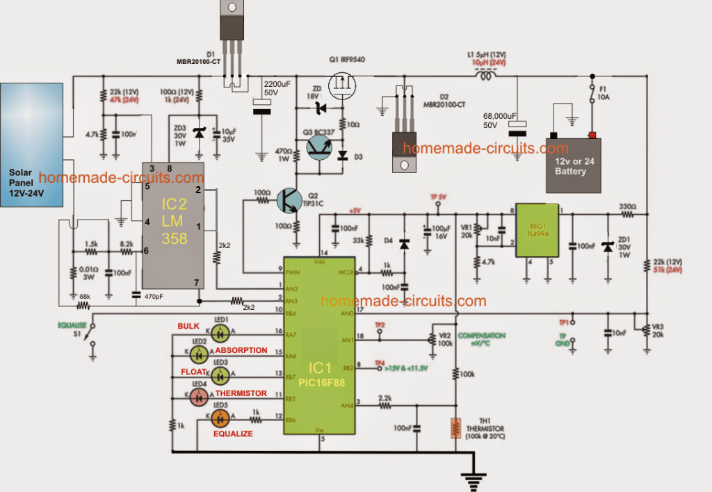
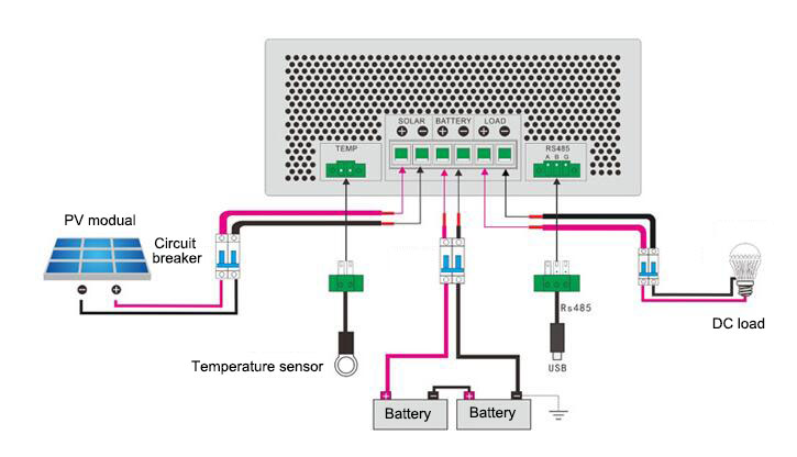
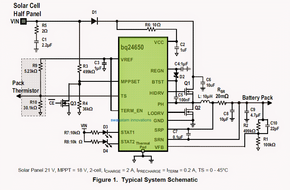
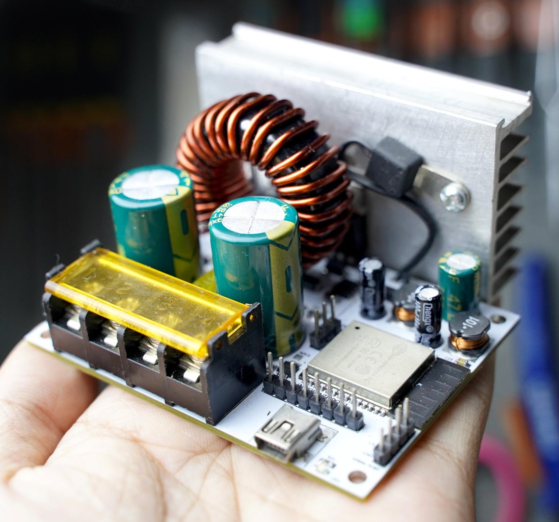
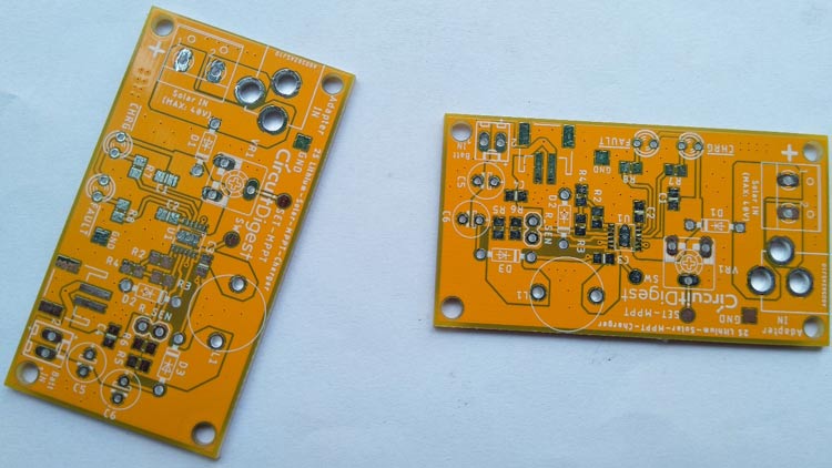
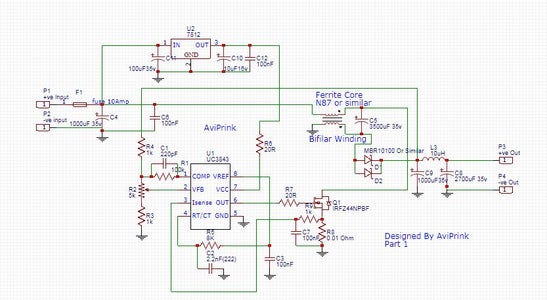
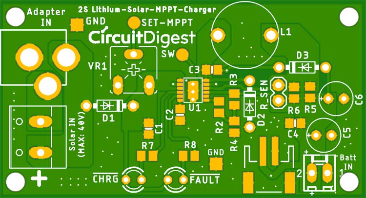
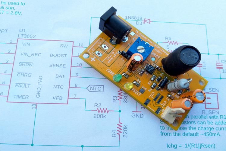
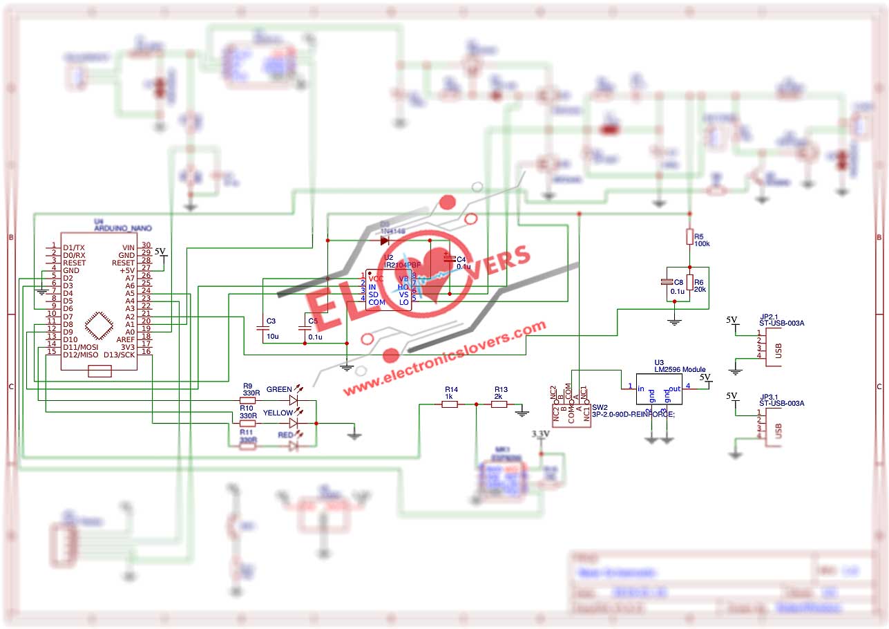
Mppt solar charger circuit diagram
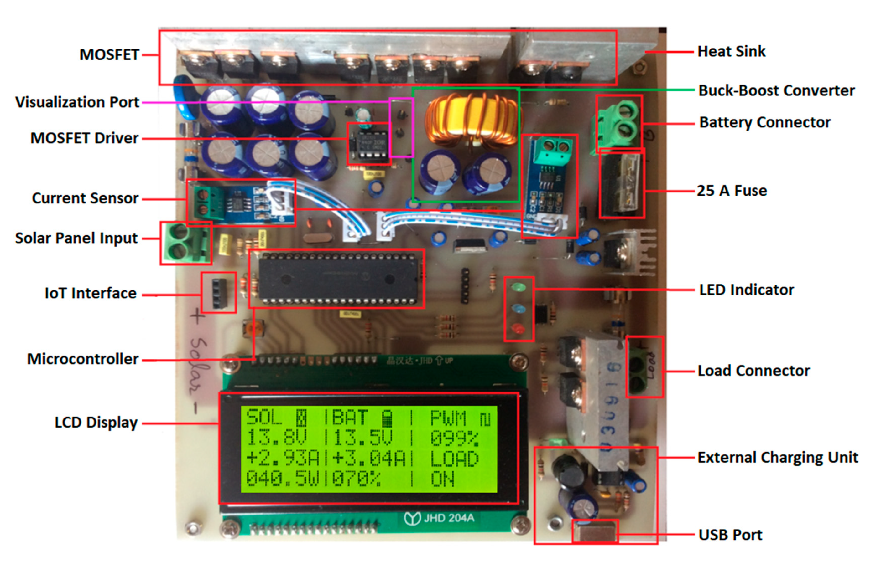
Mppt solar charger circuit diagram-To run an MPPT scan, the AD5245 code is stepped from high resistance to low resistance to operate the panel from the open circuit voltage down to 45V while the LT8611's IMON output is This project is Based on MPPT (Maximum power point tracker) algorithm 2 LED indication to show the low mid and high level of charge stat 3 LCD (×4 character ) display for

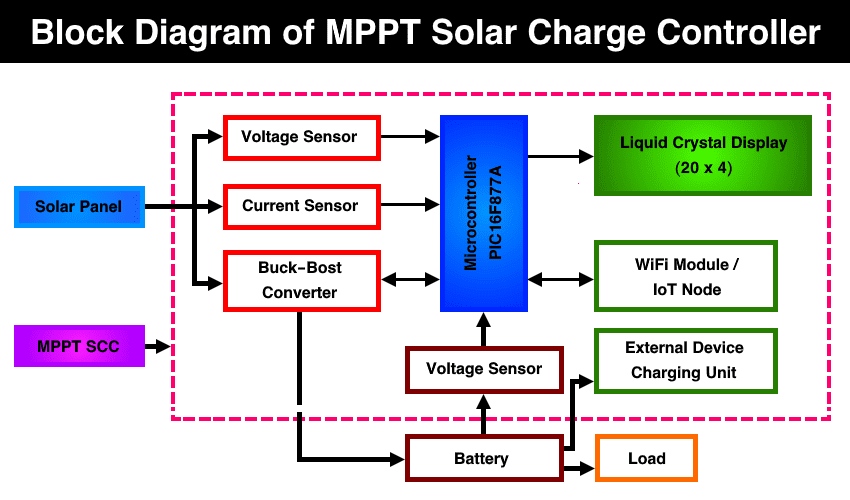
How To Make Mppt Solar Charge Controller Kiyani Solutions
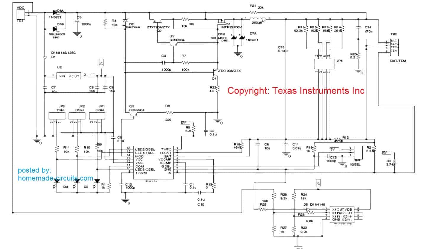
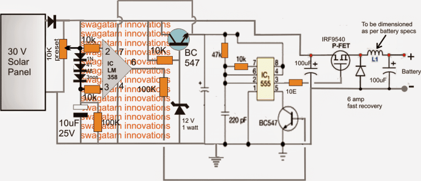
Taking a look at the given solar mppt circuit making use of IC555 we observe that the whole design is essentially put into two levels The upper voltage regulator stage and the lower24 Circuit Diagram of 12v DC Adapter 37 25 TLP250 working Circuit 40 26 Using the IR2110 as a single 28 Circuit Diagram for subsystem of PV Panel 42 29 Circuit Diagram of MPPTFor Solar Power MPPT Controller Device Application Input Voltage Output Voltage Output Current Topology NCP1294 Solar Street Lighting 1224 V A 132V A A Flyback Table 1 NCP1294
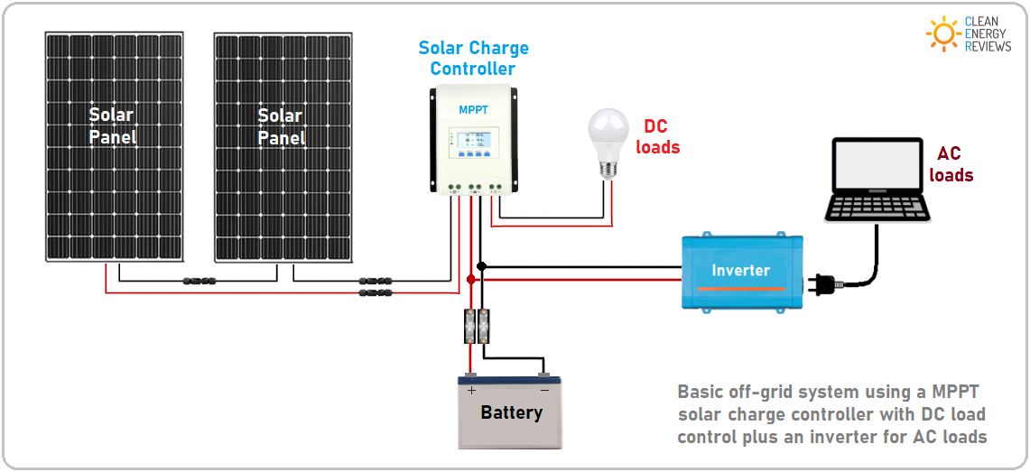
Solar Panel Charge Controller Wiring Intro Solar Panel Charge Controller Wiring Diagram and Step by Step Guide for offgrid Solar Power System Wiring Connecting the solar MPPT Charge Controller Circuit Diagram MPPT Solar Charge Controller Negative Ground vs Postive Ground In simple words, all vehicles have a NEGATIVE ground system, soThe MPPT control typically employs a microprocessor Figure 1 Solar Module IV and Power Curves Figure 2 Maximum power point tracking (MPPT) Charge Controller Circuit Diagram The output
Mppt solar charger circuit diagramのギャラリー
各画像をクリックすると、ダウンロードまたは拡大表示できます
 |  |  |
 |  |  |
 |  | |
「Mppt solar charger circuit diagram」の画像ギャラリー、詳細は各画像をクリックしてください。
 |  | |
 |  |  |
 |  |  |
「Mppt solar charger circuit diagram」の画像ギャラリー、詳細は各画像をクリックしてください。
 |  |  |
 |  |  |
 |  |  |
「Mppt solar charger circuit diagram」の画像ギャラリー、詳細は各画像をクリックしてください。
 |  | |
_5kneItTeWY.png) |  |  |
 |  |  |
「Mppt solar charger circuit diagram」の画像ギャラリー、詳細は各画像をクリックしてください。
 |  |  |
 |  | |
 |  |  |
「Mppt solar charger circuit diagram」の画像ギャラリー、詳細は各画像をクリックしてください。
 |  |  |
 |  |  |
 |  | |
「Mppt solar charger circuit diagram」の画像ギャラリー、詳細は各画像をクリックしてください。
 |  |  |
 |  |  |
 |  | |
「Mppt solar charger circuit diagram」の画像ギャラリー、詳細は各画像をクリックしてください。
 | ||
 |  | |
 |  | |
「Mppt solar charger circuit diagram」の画像ギャラリー、詳細は各画像をクリックしてください。
 |  | |
 |  |  |
 |  | |
「Mppt solar charger circuit diagram」の画像ギャラリー、詳細は各画像をクリックしてください。
 |  | |
 |  |  |
 |  | |
「Mppt solar charger circuit diagram」の画像ギャラリー、詳細は各画像をクリックしてください。
 |  |  |
 |  |  |
 |  |  |
「Mppt solar charger circuit diagram」の画像ギャラリー、詳細は各画像をクリックしてください。
 |  |  |
 |
Narrow Boat MultiPlus 3kW_12V_230V Lynx Smart BMS&DistributorsIn PV systems, insolation and temperature continuous vary Therefore, the maximum power point tracking (MPPT) techniques are used to give the highest power to the loads/batteries The MPPT
Incoming Term: mppt circuit diagram, mppt circuit diagram pdf, mppt schematic diagram, maximum power point tracking circuit diagram, mppt connection diagram, mppt controller circuit diagram, mppt inverter circuit diagram, solar mppt circuit diagram, simple mppt circuit diagram, mppt solar charger circuit diagram,


0 件のコメント:
コメントを投稿